


Back to Zenith Technical Institute Home
ELECTRICAL SYSTEMS SIMPLIFIED
By Ron Alexander
Somewhere during the aircraft building process you will encounter the often-dreaded task of installing the electrical system. It is likely that you will not receive a lot of help from your plans or assembly manual. The amount of instruction varies from one airplane to another. Usually, however, you will be left to design and install an electrical system specific to your needs. The first question to ask yourself is, “Do I want an electrical system?” You may not. If you are building a very simple airplane and have no desire for a radio or a starter, then save yourself a lot of work and the airplane a lot of weight by not installing an electrical system. Most of us will want to take advantage of the benefits derived by having a starter, radios, lights, etc. Putting in your electrical system need not be a complicated process. Like everything else involved in aircraft building, you need to know a few basic concepts. This does not mean you are required to gain the knowledge necessary to become an electrical engineer. The wiring process can be as simple or as complicated as you would like to make it. As an example, the Airframe and Powerplant Mechanics General Handbook contains over 200 pages on basic electricity, generators and motors. You can spend a considerable amount of time learning about electricity. You may decide that you want to do that for your own personal satisfaction. Personally, I am not interested in learning all of the fundamentals of electricity. I am simply concerned with how to wire my airplane. The point is, if you have a longing to learn all about electricity, the information is certainly available. Many builders do.
If you are like me and want to know only the fundamentals, then read on. Understand that I am not an expert on electrical systems but I have researched the material available and I have condensed it down to what I think you need to know to properly wire your aircraft. As Tony Bingelis so aptly states in his book Sportplane Construction Techniques, wiring an aircraft involves two basic activities:
1 – Installing the electrical equipment where it needs to be or where you want it to be.2- Connecting it to a power source (battery/bus bar, etc.) using wires.
I like that. Very simple and to the point. Each component part has a power source that is connected by a wire that has only two ends. One end is connected to the piece of equipment and the other end to a power source. Is this an oversimplification? I really don’t think so. Of course, there is a lot more involved in a proper electrical system installation but if we keep it in-perspective it really is not that complicated.
Proper planning of your electrical system is absolutely essential. Do not wait until you are in the middle of the building process to think about this. You will need to route electrical wiring, determine the best location for your battery, think about where to put a bus bar, etc. during the initial building stages. The basic steps involved in planning your electrical system are as follows:
– Locate these components within the aircraft structure
– Locate your battery, bus bars and circuit breaker panels
– Protect the components by determining proper wire size and circuit breaker/fuse requirements
– Connect component parts to an adequate power source
– Ground and bond necessary items
– Install proper instrumentation to monitor the system
– Draw a detailed schematic of the system for reference
As previously stated, you should design your system to suit your needs. Are you going to fly in marginal or adverse weather (IFR)? Will you be flying at night? If so, you will want to pay close attention to preventing a system failure. You must plan your system to operate the essential equipment for the necessary period of time you will need to land the airplane. FAR Part 23, that regulates the airworthiness of production aircraft, states that essential elements must be powered by the battery for a minimum of 30 minutes. Stop and think for a minute – 30 minutes is not that long when you are operating on a standby system. It may seem like a long time but in actuality it is minimal. On the other hand, if you are simply going to fly day VFR then you are not going to install a very elaborate system. You may only need an engine starter and a radio. No matter what your choice the basics remain the same, only the complexity of installation varies.
Prior to discussing the steps of system installation outlined earlier, I will discuss the very basics of electricity and I mean very basics. There are only a few things you really need to understand to accomplish your installation. As I mentioned earlier, if you want to plunge in deeper you certainly have that opportunity.
Basic Electricity
Let’s begin with the old familiar ohm’s law. This law is the very foundation of all principals of electricity. The law itself simply shows the relationship between electrical current flow, pressure and resistance. Current flow is measured in amperes (amps). Electrical resistance is measured in ohms. This resistance is simply an opposition to electrical flow. The pressure of electricity is measured in volts. One volt is the amount of electrical pressure required to push one amp of electrical flow through one ohm of resistance. Or another way of stating this is to say that when you pass one amp of current through a conducting object having a resistance of one ohm, the result will be a voltage drop of one volt. The formula is shown in Figure 1.
E stands for voltage or pressure, R equals resistance, and I equals current in amps.
FIGURE 1
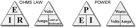
One additional formula that you will find helpful involves determining power. Power is expressed in watts and is found by multiplying the voltage times the current … P=E x I. One volt of pressure forcing one amp of flow will produce one watt of power. A watt is a unit of energy. Concerning the chart in Figure 1, if you will place your thumb over the value you wish to calculate you will either divide the other two values or multiply as indicated. As an example, if you wish to calculate R, hold your thumb over the R and divide as indicated. The temptation is to go on with basic electricity but I will easily overcome that temptation. Knowledge of these formulas will assist you in designing your electrical system.
Batteries and Alternators
Your system will undoubtedly contain a battery. We are all familiar with a battery, but what is its purpose? First and foremost it provides the necessary power to start the aircraft engine. In some aircraft that do not have an alternator or generator it may be the only source of power for all electrical items. The battery also provides electrical power in the event the generator/altemator fails. When it comes to choosing your battery you have a number of choices. Lead acid batteries are probably the most common. This type of battery has been around for years and is quite common on automobiles and aircraft.
These batteries are usually fairly inexpensive. Lead acid batteries emit explosive gases that must be vented. This will be discussed later. Another common battery is the so-called gel-cell. This is also a lead acid battery that has a material added to the electrolyte converting it into a gel state. This type of battery is less likely to spill and is often used in acrobatic aircraft. Nickel-cadmium batteries are also available. These batteries do present some maintenance problems and are not widely used on smaller aircraft. A very good choice of battery today is the recombinant gas battery (RG). They do not leak and they can be mounted in any position. The disadvantage is the price – they are usually more expensive.
Most amateur-built aircraft will require a 12-volt battery instead of a 24-volt. Most designs call for a 14-volt electrical system versus a 28-volt due largely to cost and weight differences. A 14-volt system utilizes a 12-volt battery. Even though a battery is rated at 12 volts the actual voltage will vary depending upon the charge state. Battery amperage also comes into play as we make the decision as to what type to install. Should you buy a 25 amp or 35 amp battery? Starting performance in addition to operation of essential equipment must be taken into consideration. Generally speaking, a 25 ampere-hour battery is adequate for most light aircraft. When you purchase your battery keep this thought in mind – it may be operating your emergency equipment while you shoot that low approach in bad weather after the loss of your alternator.
Alternators are simply generators that produce alternating current. They are the most common forms of electrical power on aircraft today. An alternator converts mechanical energy into electrical energy that can power our electrical components. Most alternators today are lightweight (6-8 pounds) and provide a considerable amount of amperage (typically 40 amps or more). You must calculate the needs of your entire system prior to selecting the alternator. Common ratings are 30 to 50 amps.
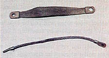
Relays, Contactors and Solenoids
A relay or contactor is usually installed to activate an engine starter. It serves to eliminate the need to run a heavy cable from the battery and starter all the way to the master switch. A contactor or relay is simply an electromagnetic switch that operates a heavy current circuit. These are often called solenoids. A large wire (usually 4 gauge) is installed between the contactor, the battery, and the starter. A smaller gauge wire (usually 18 gauge) is then run between the relay and the master switch.
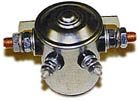
Relay
Voltage Regulators
A voltage regulator must be present to protect the battery. The charging voltage going into the battery must be controlled within a relatively small range – as an example, 13.8-14.2 volts for a typical lead acid battery at normal temperatures. This voltage varies with the ambient temperature. The voltage regulator is going to prevent battery overcharging by decreasing the alternator output as the battery nears a full charge state. Most other equipment within your airplane can withstand a wide range of voltage. Just about any solid-state regulator will control most alternators.
Circuit Protection
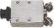
Circuit Breaker
We must protect individual electrical circuits from overloads. This is usually accomplished using a fuse or a circuit breaker. Fuses and circuit breakers are not intended to protect the equipment, rather, they are installed to protect the cable (electrical wire) attaching the power source and the equipment. Of course, in protecting the cable the equipment is also protected. Fuses will be cheaper to purchase and lighter in overall weight than circuit breakers. During flight it is easier to reset a circuit breaker than change a fuse. If you closely analyze most electrical faults they are produced by failure of an electrical device that in turn causes it to draw an extremely high amount of current. In reality, how often will you be able to solve the problem by resetting a circuit breaker or replacing a fuse? Probably not very often. A short in a wire will also cause an electrical fault.
The bottom line is that you must select the right size circuit breaker or fuse for the size wire you are running to the component part. The circuit protection should open before the wire gets hot enough to begin smoking. Another point worth mentioning is that if the circuit protection is too small for the wire size you will get a nuisance protection requiring you to reset the circuit breaker or replace the fuse even though a major problem may not exist. The following chart found in FAA Advisory Circular 4313 shows the comparison between wire size and circuit protection.
[table “” not found /]
What would happen if we did not comply with these guidelines? Let’s assume we install a 10-amp circuit breaker in a circuit connected by a 22 gauge wire. As long as everything is normal you will probably not know the difference. However, should an electrical fault occur in this circuit, the breaker may not trip until the wire gets so hot that it causes an electrical fire.
Electrical Wiring and Connectors
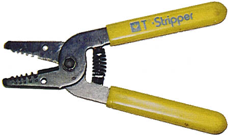
The primary concern is that you use the proper type of wire. Do not go down to your local electronic store and expect to get the proper wire for your aircraft. The best type of wire to use in your airplane is MIL-W-22759/16 unshielded wire or MIL-C-27500 shielded wire. Both types of wire are manufactured to the military specification number given and they are insulated with a Teflon-type of material called tefzel. The wire is rated for 600 volts. Teflon and PVC wire is also often used but after researching the problems involved I would stay with tefzel wire. Sure, you can probably save a few dollars on surplus electrical wire but is it really worth it? Wires are manufactured in various sizes with 22 gauge being the smallest you will normally encounter on your airplane. To provide an example, 22-gauge wire is about .025 inches in diameter and is comprised of several strands of smaller wires.
Connectors
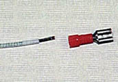
Tefzel wire & connector
Grounding wires
As mentioned under circuit protection, the size of the wire is of utmost importance. The wire size will be selected based upon the amount of current the wire will carry and the required length of the wire. The voltage drop resulting from a long length of wire can be significant. Fortunately, AC43-13 provides charts showing the relationship between wire length, size and amperage.
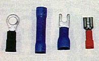
A large number of electrical problems are the result of poor connections between the electrical cables and the various components of the system. Most cables are corrected with “crimp-on” connectors, such as ring-end terminals or butt splices. Often a solder joint will be used to complete the connection. I would recommend the use of “crimp-on” connectors whenever possible. Solder joints are subject to breaking or weakening when subjected to vibration. If you use a solder joint, be sure to support the wire near the joint to prevent flexing. You will find the need for soldering to be more common during your radio installation.
Selection of the proper solderless connector is easy because the connectors are color coded. The coding is as follows:
Color of Connector – Size of Wire
Red R – 18-20-22 gauge
Blue B – 14-16 gauge
Yellow Y – 10-12 gauge
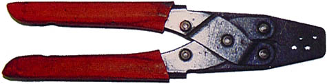
A special tool is used to crimp the connection. Approximately 3/16 inch is stripped away from the wire, using wire strippers, and the wire inserted into the connector. The tool is then used to make the crimp. You then check the connection by slightly pulling on the terminal and wire.
It is also recommended that you insulate the terminal connection using heat shrinkable tubing. You must remember to place the tubing over the wire prior to assembly.
Bus Bars
No doubt you have heard the electrical term bus bar. A bus bar is very simply a central point where wires from electrical equipment are grouped together and attached to a metal bar that is then attached to a power source. Without a bus bar we would have to connect every electrical component directly to the power source. This would be very complicated and impractical. Normally, one terminal of each circuit protector (circuit breaker or fuse) running from the electrical component is attached to the bus bar. The power to operate all of your electrical items is then obtained from one common point. This is generally accomplished using a strip of copper large enough to tap a hole for each circuit breaker required. This would usually be about 1/8-inch to 1/4-inch thick and 1/2-inch wide. They must be long enough to accommodate the number of breakers. If using fuses, a heavy copper wire is often used that is soldered across one terminal of each fuse. Doing either of these creates a bus bar.
Switches
A lot of text could be written concerning electrical switches. You will need to determine what type of switch you desire and where you want it located. Even though there are many switch types they all provide the same type of function. That function is the control of an electrical component. Listed below are various types of switches you may encounter and their description.
Single-pole, double-throw: Two circuits but not at the same time
Double-pole, single-throw: Two circuits at the same time
Double-pole, double-throw: Two circuits with each throw
A pole is the movable metal contactor of the switch. The number of poles will equal the number of external terminals on the switch. The throw is the number of circuits each pole can complete. As an example, a simple toggle switch with an on-off position is an example of a singlepole, single-throw. A rocker switch is another example.
Another available switch option is the combination switch/circuit breaker. This switch also serves a dual function as a circuit breaker. Many custom builders are using this type of switch. Whatever type of switch you install you must be sure the voltage and amperage ratings are adequate for the circuit you are completing.
Grounding and Bonding
Grounding is the electrical connecting of a conducting object to the primary structure to provide a return path for the electrical current. On metal aircraft the main frame, fuselage, or wing is used. The battery is generally grounded to the engine crankcase and from the crankcase a ground wire is run to a ground bus behind the instrument panel. Bonding, on the other hand, is the electrical connecting of two or more conducting objects not otherwise connected. Often, in composite and wood aircraft, the bonding connection will also provide the ground connection for an electrical component. Bonding provides a conductor for the purpose of eliminating the build-up of static charges. This will also reduce radio interference. Specific methods of grounding and bonding will be discussed in the next issue.
So, as you can see, installation of your electrical system need not be complex. There are a number of sources for information concerning basic wiring practices. Tony Bingelis’ books are excellent. Bob Nuckolls is also a recognized electrical expert and has written many articles concerning the subject. He also has a regular newsletter called The AeroElectric Connection. Information obtained from this publication will be very helpful to the first time builder.
Part 2
Wiring your custom built aircraft is not an overwhelming task. It is a part of the building process that may appear to be staggering but when analyzed it is actually fairly simple. The problem encountered by several builders is the lack of information presented in many kit assembly manuals. Usually the basics are presented in the manuals but details are often omitted due to the varying requirements of each builder. Many individuals want to have a very simple electrical system with minimum equipment while others desire sophisticated avionics, electrical gear and flaps, etc. Because of this diversity, many kit manufacturers do not spend much time outlining the electrical system.
This article follows an earlier discussion in last month’s issue on the basic knowledge you will need to wire your aircraft. This month I will detail the actual steps involved in installing your electrical system. Remember, all you are going to do is install the equipment you want in the desired location and then connect each component part to a power source. This narrows the installation process down to a very simple concept. You can make the wiring task as complicated as you like or you can keep it very basic and understandable.
The basic steps involved in wiring your amateur-built airplane are as follows:
2 – Locate the equipment in the aircraft
3 – Locate the battery, bus bars, and circuit breaker/fuse panels on the airframe
4 – Calculate wire size and circuit breaker/fuse requirements
5 – Connect the electrical equipment to a power source
6 – Ground and bond properly
7 – Install proper instrumentation to monitor the system
8 – Complete a detailed schematic drawing of the system
Determining Equipment Requirements
You may want a very simple electrical system with only a starter and alternator. On the other hand, you may be building an aircraft that requires a somewhat sophisticated system for maximum utilization of the aircraft design. The first step is to decide what electrical equipment you want to install on your aircraft and then calculate the current draw in amps each piece will require. Your aircraft may have electrical gear and flaps. You may want strobe lights, a starter, landing lights, cooling fans, electric elevator trim, etc. Decide now what to install then calculate the current draw of each item.
The current draw is often listed on the electrical component or it is available from the manufacturer. You will need to know the current draw in amps. This can be determined by using Ohm’s law or, more commonly, the wattage will be given and you can then use the power formula expressed as Power = Voltage X Current. Using this formula we can then find the current draw in amps by dividing the watts by the voltage. This number will be needed later to determine the size of wire needed for the piece of equipment.
You should also decide if you are going to install a 14-volt system or a 28-volt system. The majority of custom-built aircraft will use a 14-volt electrical system. Of course, you want to ensure proper alternator output to power your electrical equipment. Additionally, begin to develop your schematic diagram at this point. Beginning a basic diagram at this time will make it easy to build on as you install the system.
Locate the Equipment
It is very important to plan where you will place your electrical items. If you are planning to install strobes, landing lights, navigation lights, etc. you will want to route the wiring needed for both power and ground. In many aircraft designs, this must be completed during the early phase of assembly. Otherwise, you may find that you will be unable to route electrical wire or certainly find it to be a very difficult task. After locating equipment, route the necessary wiring being sure to identify each wire. You can identify each wire by using tape that is folded over and marked. The size of wire will be discussed in a later step. Use black wire for grounding of equipment so it is easily identified. Continue your schematic as you locate equipment.
Locate the Battery, Bus Bars and Circuit Breaker Panels
Locate the battery as close to the engine starter as possible. This is desirable due to the high electrical draw the starter requires. The battery also must be protected from high temperatures and located in an accessible area for ease of servicing. Weight and balance will also be a consideration. Often a battery will be located in the aft portion of a fuselage to balance the aircraft. Be sure to properly vent the battery.
Recalling from the previous article on electrical systems – a bus bar is a central point where wires from electrical equipment are grouped together on a piece of metal (usually copper) and the metal bar is then connected to a power source. You may also have a grounding bus bar to locate in your aircraft. Several builders are using a central grounding point for all equipment rather than grounding to the fuselage frame. Composite and wood aircraft often use this type of grounding. Bus bars are usually located near the instrument panel for ease of installation. You will want them to be somewhat accessible but not exposed where they could cause injury.
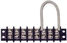
Terminal Strip
Circuit breaker/fuse panels are usually located in the cockpit area where they can be reached by the pilot during flight. This will normally be under an instrument panel or as a part of the instrument panel. Circuit breaker panels are also mounted on side panels. Often a bus bar will be used to connect circuit breakers together. This will allow the circuit breaker installation to serve as a bus bar. Circuit breakers can be grouped in a power bus by tapping holes in a copper strip and securing with small screws. Either terminal of the circuit breaker can be used to connect to the bus bar but you will probably find it more convenient to attach to the top terminal. The bus bar attaching the circuit breakers is then attached to a power source eliminating the need for a separate bus bar. You will probably want to fabricate more than one circuit breaker panel. These panels will then be located in different areas.
Aircraft builders often use fuse panels. A fuse bus bar is constructed using a heavy piece of copper wire and soldering the wire to the terminal of each fuse. This will also create a power bus. Most fuses require the use of soldered connections. Fuse panel installations will be cheaper than circuit breakers but you will have more difficulty changing a fuse in flight versus resetting a circuit breaker.
Calculate Wire Size and Circuit Breaker Size
Calculation of wire size will be necessary during the initial building phase. As discussed earlier, you will want to route electrical wires prior to completing the construction of the wings and fuselage. Proper wire size is critical to a safe electrical system. The match between the wire size and circuit breaker/fuse size is also critical. To determine the size of wire you will need, refer to FAA Advisory Circular 43-13. Two charts are presented; one displaying continuous flow and the other intermittent flow. What is the difference? Most aircraft electricians agree that any piece of equipment that operates more than 2-3 minutes at a time is considered continuous flow. That encompasses most items on an airframe. Intermittent flow then would obviously involve items that operate momentarily. An example of intermittent flow items is a landing gear or flaps. With that in mind, the builder enters the appropriate chart (intermittent or continuous) with the current draw of the equipment being connected to determine the proper wire size. The wire size is based upon the amount of current the wire will carry and the length of the wire.
Again, we are going to use Tefzel wire that is sold under military specification MIL-W-22759/16 for unshielded wire and MIL-C-27500 for unshielded wire. Resist the temptation to go to your local electronic store and purchase wire. Most of your installation will be completed using unshielded wire. Be sure to use good quality wire cutters and strippers to cut and prepare the wire. The same applies to the crimping tool you will need.
Connect Equipment to Power Source
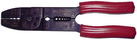
Care should be taken to properly connect all equipment to the power source. Most electrical problems encountered during the initial installation phase can be traced to a poor connection. Crimp on connectors must be carefully installed on a wire that has been properly cut. Cut about 3/16-inch of insulation away from the wire. Use a good quality crimping tool. The correct size connector should be used. The connectors are color-coded red for 18-22 gauge wire, blue for 14-16 gauge, and yellow for 10-12 gauge wire. Taking your time as you crimp each connector will save you hours of troubleshooting when you power up your system for the first time. Check the connection physically by pulling on the wire and connector. Protect the connection with the use of heat shrinkable tubing. This tubing will insulate the connection protecting it from electrical faults. Check each connection electrically using an ohmmeter. Equally as important are solder connections. Proper soldering techniques must be used. Practice your soldering before you attempt it on your aircraft.
Routing of wires is also very important. After marking the wires you can group them into bundles. This is often very convenient when running several wires from one area to the bus bars. Several acceptable practices for routing of wire follows:
– Do not allow bundles to have too much slack. Using normal hand pressure you should not be able to deflect the bundle more than one-half inch.
– Separate wires and bundles from flammable fluid lines. If this is not practical, always run the fluid lines below the wire bundle and separate the two by 6 inches or more.
– Protect wires in high temperature areas by using insulating sleeves.
– When running bundles or wires through cutout areas such as bulkheads, protect from chafing by using a rubber grommet.
– Splicing of wire is permitted but should only be used if necessary.
– No more than one splice per connection is recommended.
– The splice should not be within 12 inches of a terminal end.
– Be sure wires are at least 3 inches from control cables. If not possible, use a guard to prevent contact.
Proper routing of cables is necessary to prevent the wires from coming in contact with other parts of the airplane. This can easily occur as a result of movement or vibration. A wire can obstruct movement of a control or it can be damaged causing a short. A shorted wire can be very difficult to locate. This is one other reason to be very careful during the entire installation process.
Grounding and Bonding
Grounding is defined as the electrical connection of a conducting object to the primary structure to provide a return path for the electrical current. Bonding is the electrical connecting of two or more conducting objects not otherwise connected. The difference between the two can be confusing. A simple explanation is that bonding may not always result in a ground. It may only connect objects. Metal aircraft have a built in ground – the airframe. The main frame of a metal aircraft can be used as a ground. Many builders will use a grounding strap and connect the piece of equipment to be grounded to the frame itself. Another method of grounding is to use a common grounding bus bar. This bar can be located under the instrument panel and used to connect all ground wires from equipment throughout the aircraft. This is referred to as a central grounding point. The grounding bus bar is grounded to the engine of the aircraft. In this case two wires must be run to each piece of equipment – the power wire and the ground wire. This type of grounding is more common in composite and wood aircraft. Both of these aircraft require some form of ground other than their airframe. Wood and composite material do not conduct electricity.
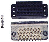
Grounding block and pin connector may be used as a central grounding point.
Many wood and composite aircraft builders will use a bonding network that interconnects all grounds and then terminates at the engine providing a ground. It is a metallic network installed specifically to provide a ground. This helps explain the difference between bonding and grounding. The bonding network must be grounded.
The wire used for grounding must be adequate to carry the electrical load. A braided grounding strap is often used. You should also check each grounding connection with an ohmmeter. To be sure you have a good connection between two metal parts the surfaces must be completely clean. Any protective coating should be removed. This can be accomplished by sanding the surface. After the bonding connection is completed, the area can be protected using a varnish. For an excellent discussion on grounding and bonding refer to the AeroElectric Connection written by Bob Nuckolls.
Install Instruments to Monitor the System
You want to know the status of your electrical system as you operate your aircraft. Proper instrumentation can alert you of actual or potential problems. The battery ammeter is a necessary instrument. You want to know the state of your battery at all times. The ammeter indicates the amount of current flowing into or out of your battery. The instrument you install should show both charging and discharging current. You can then interpret the condition of your battery and its charging system with this instrument. After 1 hour of flying a typical battery should reach a fully charged state. The indication of this would be a slight indication on the positive side of the ammeter. The ammeter may be used to detect a number of problems. Be sure to install this instrument.
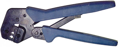
Molex pin crimping tool
Another instrument you may want is a voltmeter. This instrument will monitor the electrical system voltage. In a 14-volt electrical system, a reading of 13-15 volts would be normal. Readings less than 12 volts are usually indicative of a problem. For instance, a very low reading could mean that the battery is failing.
A warning light may also be installed as an added method of monitoring the electrical system. This can be in the form of a light used to monitor an overvoltage or under voltage condition. This could be very helpful in detecting a high voltage condition that might require shutdown of the electrical system or warn of alternator failure. An overvoltage light or a higher than normal load could also be the first warning of an impending electrical fire. The light may allow you to detect the problem before it becomes too serious.
The importance of monitoring the electrical system becomes even more critical if you are going to be flying at night or IFR. You will want to know the status of your battery, in particular. If you lose your primary source of electrical power, the alternator, you want to know that you can depend upon your battery to supply power to the essential items necessary for an immediate landing.
Complete a Schematic Diagram
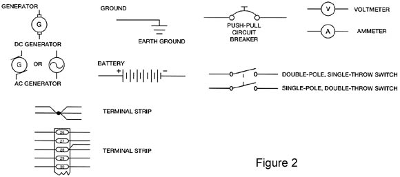
Your schematic diagram is nothing more than a road map of the electrical system. The symbols used in electrical diagrams vary from one manufacturer to another. Some of the symbols are fairly universal but you still may find differences. These symbols are actually a language of electrical components and are sometimes difficult to understand. I would not be too concerned about the symbols. More importantly, you want to map out your system very simply so you can understand it. Mapping it out allows you to trouble shoot electrical problems during installation and at a later time when you may encounter a problem. Use as many common symbols as possible so that when another person tries to find a problem at a later date they will be successful. You can indicate the length of wires along with the size on the schematic. Define each piece of electrical equipment along with part numbers if you desire. Show where bus bars and circuit breakers are in relation to the system and physically in the airplane. Several common symbols are found in Figure 2. Anything you can do to map out your system will be most helpful at a later date. Build your schematic diagram as you build your electrical system. This will be much more effective than trying to remember everything after it is installed. Build it to suit your needs but build it so that it can be understood by someone else who may be helping you with a problem or a new owner.
Hopefully, the articles presented this month and last will take some of the mystery out of electrical systems as they apply to amateur-built aircraft builders. You can certainly dig in much deeper than I have in these two articles. There are several books available that will explain in depth electricity and the installation of an electrical system. I have chosen purposely to keep this as simple as possible. I do not think you have to understand all of the intricacies of electricity to properly design and install your electrical system. Only a very basic understanding is necessary along with proper planning of the system. Planning, as always, is key during this phase of construction. Plan your electrical system early in the building process. Talk to other builders of similar type aircraft to see how they have overcome electrical problems. Attend the EAA/SportAir workshop on Electrical Wiring and Avionics. You will be given an opportunity to understand and actually practice the techniques needed for your installation at this workshop. Most of all, keep it as simple as possible. Outline your system, determine wiring and circuit breaker requirements, connect everything properly, and install instruments to monitor the system. Be sure to detail a schematic diagram for future reference and problem solving.