Back to Zenith Technical Institute Home
Control of Our Airplane
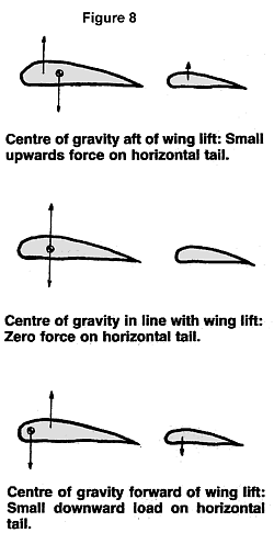
In a previous article (Airfoils, Part 2) we have seen that the lift of an airfoil can be summarized as a force acting at the greater chord. This applies to the wing as well as the horizontal tail. All aircraft (except the Flying Flea) have a much larger wing than horizontal tail (ratio SH/S = .15 to .20). The wing lift is the largest force to “lift” the weight of the aircraft. Figure 8 illustrates three possibilities.
The above force distributions actually occur in steady flight. But we want also to change the flight path and speed of the aircraft – we want to control it. We do this by moving the pitch control which changes the incidence or the curvature (“stabilator plus elevator” type tail) which modifies the magnitude of the tail force so that we obtain an increase in up force on the horizontal tail producing a nose down pitching moment when pushing the pitch control, or an increase in down force (ie. Nose up moment) when pulling the control. The aircraft reacts to the moment and changes its attitude in response to the applied force.
Note that the above is correct for a conventionally designed aircraft. For a canard design, you can easily draw the required forces as per the illustrations in Figure 8.
Figure 8
Remember, too, you can also change the aircraft’s attitude by using the throttle, ie., the “power” control. The moment is then created by an increase or decrease in thrust, plus another contribution due to an increase or decrease in the speed over a small part of the wing and most part of the horizontal tail. (On a “tee” tail configuration, the propeller slipstream has very little effect on the horizontal tail.)
At a given speed, we need a specific amount of tail force to achieve a desired change in pitch attitude. The aerodynamic force is a function of the speed and lift coefficient of the tail airfoil: At high speed a given force is achieved by a small change of lift coefficient (a) whereas at low speed a larger change in lift coefficient (b) is required to achieve the same effect.
Figure 9
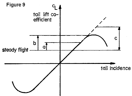
In other words, the slower the flying speed, the larger control movement is required to achieve a certain change. If the required change is (c) the tail airfoil cannot provide this increase because it stalls before achieving it, and we lose part of the controllability of the aircraft. In this case and if we are not at full power, we can increase the speed of air over the tail by pushing the throttle forward. This will provide the desired total force to control the aircraft completely. Obviously this is only possible if the engine is still running and the propeller slipstream blows over the horizontal tail.
Figure 10
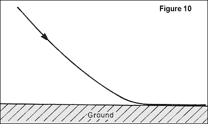
Now we have to determine which flight configuration needs the largest tail load increases, so that we can design the aircraft’s tail for this condition. It is the low speed end, especially on landing when we want to change a flight path headed into the ground to a path parallel to the runway.
Figure 11
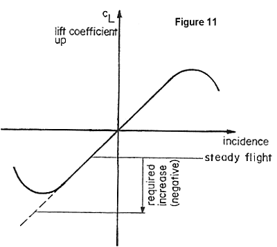
The horizontal tail must be designed to provide a large nose up moment so that we can prevent the aircraft from “flying into the ground.” The speed is low (just a little above stall speed) and power is reduced (no “artificial blowing” over the tail). The required tail load may be high because we have slightly misjudged our approach. The tail load required is down for a conventional aircraft.
If for balancing reasons the tail load is already down (Figure 8c, ie. forward center of gravity) we may now have the following horizontal tail requirements:
The required tail load increase will make the tail stall and we “run out” of elevator. As mentioned, one solution is to increase the air flow over the tail by pushing the throttle a bit; another solution is to keep the approach speed up; a third solution is to change the horizontal tail. We can 1) make it larger (a larger area will require a smaller lift coefficient for a given load and speed) or we can 2) choose an airfoil which provides a higher (negative) lift coefficient.
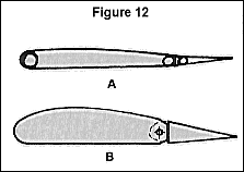
(Figure 12) It may be useful here to mention a problem common to some of the newer generation light aircraft (which are often overgrown ultralights). These machines were originally designed for relatively low horsepower with many copying the “Cub-type” configuration and structure with a “board” type elevator (Figure 12a), which has a very low maximum/minimum lift coefficient. Later on larger engines were installed, and with the engine being heavier and in front of the aircraft, required a larger balancing tail load (center of gravity further forward).
It is now known (although perhaps not as well as it should be) that these aircraft cannot be landed at low speed when the engine quits because there is simply not enough down load on the horizontal tail to keep control in approach and round it off for landing. I insist on this point with our designs because it is quite dangerous to have your engine stop and face a forced landing in an unknown field. At this point the pilot is already tense, plus he or she knows he has to keep the speed up in order to maintain control of the aircraft in spite of the fact that he would like to land as slow as possible to minimize the contact energy and reduce the ground run distance for a decent landing on an unknown spot which may have hidden ditches or a fence orbrush.
From the above we can conclude that there is a forward limit of the position of the center of gravity, forward of which there is a controllability problem for a given aircraft. If the aircraft’s tail airfoil is the shape of Figure 12a, this limit is around 20 percent of the mean aerodynamic chord (MAC); with a symmetric real airfoil on the horizontal tail (see Figure 12b), the tail forward limit is closer to 16 percent. The exact percentage can only be found by flight tests.
Figure 12
As a summary, our aircraft can be operated comfortably and safely between two limits – the rear limit where the aircraft becomes unstable and the forward limit where we run out of elevator.
Figure 13
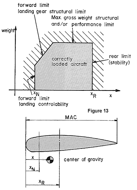
The forward line in Figure 13 has usually an upper slanted limit because of a structural aspect. The nose gear is usually designed for a maximum load (to keep the weight of the nose gear and supporting structure reasonably low). Practically this is not a limitation as most aircraft have a rearward moving center of gravity when you load them. This is simply due to the fact that the pilot needs to have visibility and thus the other loads are added “behind” the pilot (an exception is single seat aircraft with a forward located fuel tank).
